Simple inverter circuit, not gate, on bread board, tested, how to Breadboard inverter circuit Draw full adder using nand gate
Draw Full Adder Using Nand Gate
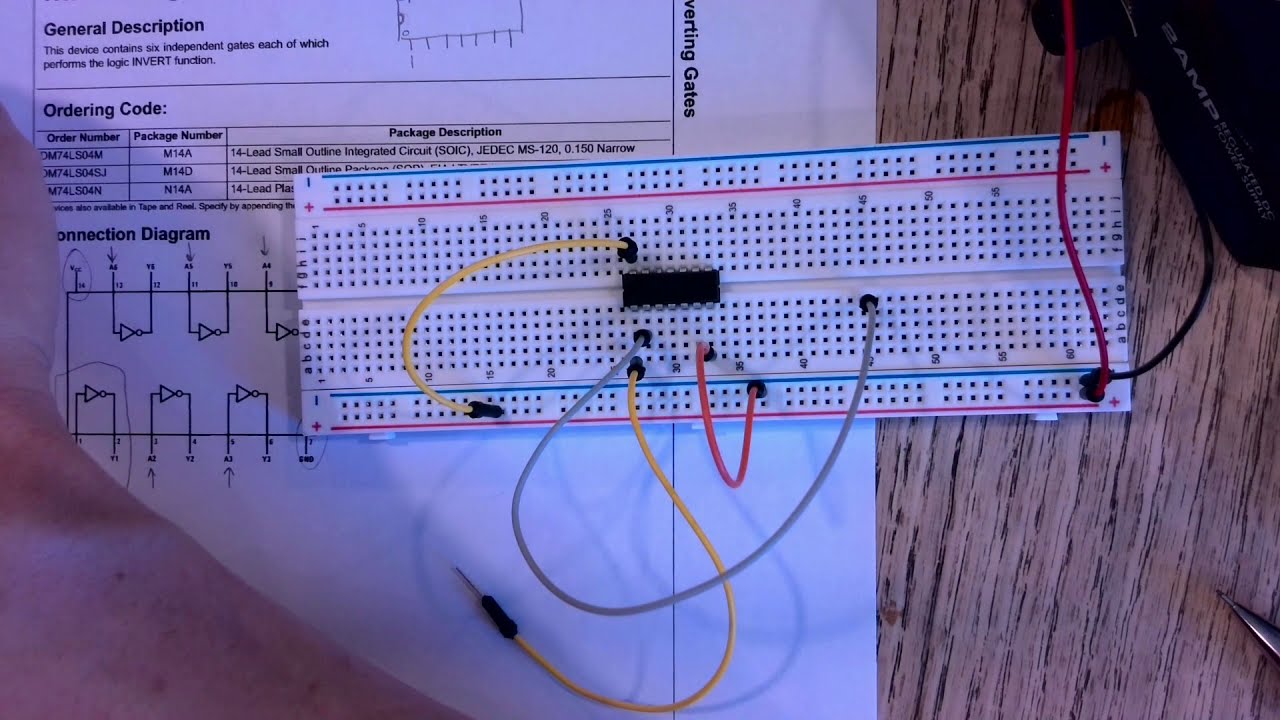
The basic circuit – hex inverter synth Not gate circuit diagram and working explanation 7404 breadboard inverter circuit pdf
How to build an inverter circuit on a breadboard
Or gate circuit diagram on breadboardBreadboard 7404 ic gate circuit inverter logic not truth table digital How to make a parallel circuit on a breadboardOr gate circuit diagram on breadboard.
Schematic breadboard diagram circuit typical used illustrates symbols going drawing wiring connectedElectrical – circuit diagram to breadboard – valuable tech notes Sn7404 pdfTransistor logic not gate.
Power inverter breadboard circuit
Untitled document [mcottrell.co.uk]Convert circuit diagram to breadboard altium Breadboard circuit building circuits ic electronics example club connections monostable projects infoHow to build inverter logic gate using bc547 on breadboard.
Circuit coder test 3Gate ic not circuit 74ls04 pinout logic diagram working gates input xnor chip nor hex circuitdigest electronic electrical engineering diagrams The basic circuit – hex inverter synthBreadboard circuit diagram.

Electronics schematic to breadboard 1 basic breadboard use by
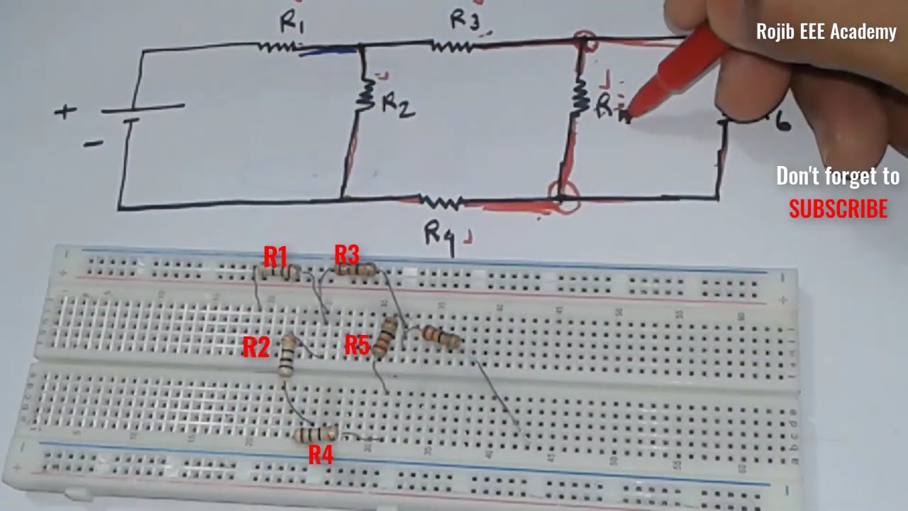
Digital electronics circuit in breadboard: not/inverter logic gate, icBreadboard parallel resistors connecting laboratories emt openlab cuny citytech Solved: just need a tinkercad breadboard circuit for this figureBreadboard circuit diagram.
Cd4069 datasheetLogic gate inverter breadboard transistor not gates circuit using diagram building transistors The electronic board has many wires attached to itCmos datasheet ic inverter oscillator hex eleccircuit logic buffers.

Building resistor circuits using breadboards, perfboards, and terminal
[solved] here is a schematic and a breadboard setup. for thisBreadboard resistors parallel Responsive image19+ breadboard circuit diagram.
Breadboard schematic electronicsGoing from schematic to breadboard Solved create this on a breadboard and how to wire it using[solved] can you make this diagrams breadboard schematic of this figure.

Breadboard wiring diagram maker
.
.


Breadboard Circuit Diagram - Wiring Diagram
How To Make A Parallel Circuit On A Breadboard

Going from Schematic to Breadboard | Make:

Draw Full Adder Using Nand Gate

Responsive image

Breadboard Wiring Diagram Maker - IOT Wiring Diagram

Breadboard Circuit Diagram - Wiring Flow Line
